$ cd ~/projects/mark85
MARK 85
Iron Man suit firmware: four limb IMUs drive synthesized stereo servo whir and repulsor charge-up.
- hardware
MARK 85
Wearable Iron Man suit firmware: four limb IMUs in, synthesized servo-whir and repulsor charge-up out, in stereo.







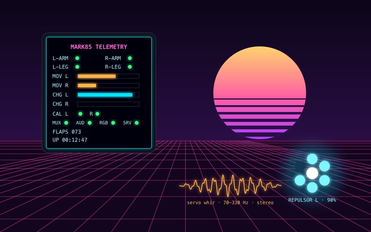
Every time the wearer moves, the suit answers. An MPU-6050 on each limb feeds a fully procedural sound synthesizer on an Arduino Nano ESP32 (ESP32-S3): movement becomes an electro-mechanical servo whir whose pitch and loudness track how hard the limbs are working, and raising an arm charges that hand's repulsor with a rising sweep and a 7-pixel LED jewel that fills as it powers up. Left limbs play through the left speaker, right limbs through the right — two independent I²S amplifiers, one per side. A vaporwave LCD shows boot splash and live telemetry. No samples, no bitmaps: every sound and every pixel is generated at runtime.
 ┌────────────────────────┐      What the 240×280 LCD shows after boot
 │    MARK85 TELEMETRY    │      (layout of display.cpp's monitor screen)
 │ L-ARM ●     R-ARM ●    │  ←   limb online / offline dots
 │ L-LEG ●     R-LEG ●    │
 │ MOV L ▕██████░░░░░▏    │  ←   movement intensity, per side
 │ MOV R ▕███░░░░░░░░▏    │
 │ CHG L ▕█████████░░▏    │  ←   blaster charge, per hand
 │ CHG R ▕░░░░░░░░░░░▏    │
 │ CAL  L ●   R ●         │  ←   boot pose calibration result
 │ MUX ● AUD ● RGB ● SRV ●│  ←   subsystem health from setup()
 │ FLAPS 073              │
 │ UP 00:12:47            │
 │ ╲ ╲ ╲  ╲ │ ╱  ╱ ╱ ╱    │  ←   neon grid-floor footer
 └────────────────────────┘
✨ Highlights
- Motion-reactive stereo sound. Each side's intensity is the busier of its arm and leg gyro magnitudes (saturating at 200 °/s), smoothed with a fast attack (50 ms) and a slower release (300 ms) so the sound trails off like spinning-down machinery.
- Procedural servo-whir voice. A 70–330 Hz fundamental, an inharmonic partial at 2.71× for gear mesh, and a noise hiss, under an attack/release envelope that snaps to true silence at rest. Rendered at 22.05 kHz, 16-bit mono per channel.
- Dual-hand repulsor blasters. Raising an arm past ~120° from its rest pose charges that hand's blaster over ~1.2 s (lowering it winds down in ~0.3 s). Charge drives a 180 → 1430 Hz rising sweep with vibrato, mixed onto that side's channel, and the jewel LED: the ring fills clockwise from deep blue to cyan-white and the center ignites white once primed.
- Mount-agnostic pose detection. During the 5 s boot splash the wearer holds a neutral pose while each limb averages its gravity vector. Blaster detection measures the angle against that captured "down", so it works no matter how a sensor is strapped on — and a bad calibration leaves the blaster safely off.
- Vaporwave UI. A glitch-titled "JARVIS" splash with a slit sun, neon helmet silhouette, arc reactor and an animated perspective grid floor, then a live telemetry screen — all drawn from GFX primitives.
- Boot jingle. A 1.9 s retro power-up — chiptune arpeggio, servo wobble slide, final ding — on both speakers while calibration runs.
- Tested off the hardware. All behavior lives in hardware-free
domains/code with 70 Unity test cases that run on the host and in GitHub Actions.
🧠 How it works
The firmware is split into thin drivers (one per peripheral, I/O only) and
pure domains (behavior, no Arduino headers, time passed in as a parameter).
main.cpp only schedules: there is no delay() in the loop, and every
subsystem runs on its own millis() cadence.
flowchart LR
    subgraph IN["Sensors · every 20 ms"]
        IMU["imu_array<br/>4× MPU-6050<br/>via HW-617 mux"]
    end

    IMU --> PHASE{"boot_sequence<br/>first 5 s?"}

    PHASE -- "splash" --> CAL["pose_calibration<br/>average gravity per limb"]
    PHASE -- "splash" --> JINGLE["boot_sound<br/>power-up jingle"]
    PHASE -- "splash" --> SPLASH["display<br/>animated grid floor"]

    CAL -. "arm 'down' reference" .-> BLAST
    PHASE -- "monitor" --> MI["motion_intensity<br/>L: max(L-arm, L-leg)<br/>R: max(R-arm, R-leg)"]
    PHASE -- "monitor" --> BLAST["blaster_charge<br/>arm-raise hysteresis<br/>0..1 charge ramp"]

    MI --> SYN["sound_synth<br/>servo-whir voice"]
    BLAST --> CHG["sound_synth<br/>charge-up voice"]
    SYN --> MIXL["suit_sound<br/>per-side mix"]
    CHG --> MIXL

    MIXL --> AL["audio_out · I²S0<br/>left speaker"]
    MIXL --> AR["audio_out · I²S1<br/>right speaker"]
    JINGLE --> AL
    JINGLE --> AR

    BLAST --> LED["rgb_leds<br/>2× 7-pixel jewel · ~30 Hz"]
    MI --> TEL["telemetry_view + display<br/>meters & status · 10 Hz"]
    BLAST --> TEL
    SWEEP["servo_sweep<br/>0→180→0 every 8 s"] --> SRV["servos<br/>4× MG996R · 50 Hz"]
| Cadence | What runs |
|---|---|
| 20 ms (50 Hz) | Read all four IMUs; calibration or motion/blaster step |
| every loop pass | Top up both I²S DMA queues with 128-sample chunks |
| 33 ms (~30 Hz) | Blaster jewel LEDs (or splash floor animation) |
| 20 ms (50 Hz) | Servo angle update |
| 100 ms (10 Hz) | Telemetry screen dynamic values |
Calibration acceptance. A limb's neutral-pose window is accepted only with
≥ 50 samples, a mean magnitude of 0.8–1.2 g, a magnitude spread under 0.35 g
(i.e. the limb was still) and a directionality ratio ≥ 0.6. Otherwise the
telemetry CAL dot stays dim and that side's blaster is disabled.
Blaster hysteresis. Raised when the gravity/down cosine drops below −0.5 (~120°), lowered when it climbs back above 0 (~90°), with a 150 ms debounce so a wobble at the threshold can't flicker the charge.
Status: the servos currently run a slow bench-test sweep (
servo_sweep), shown asFLAPSon the telemetry screen; it is a placeholder that will become flap control.
🔩 Hardware
| Component | Qty | Interface | Notes |
|---|---|---|---|
| Arduino Nano ESP32 (ESP32-S3) | 1 | — | 3.3 V logic on all GPIOs; powered via VIN |
| LiPo 2S battery (7.4 V nominal) | 1 | — | Main power input |
| Buck converter, 7.4 V → 3.3 V | 1 | — | Peripheral rail (mux, IMUs, LCD, amps, RGB) |
| Buck converter, 7.4 V → 5 V | 1 | — | Servo rail only |
| Inline fuse F1 (5 A) | 1 | — | Battery master fuse |
| Inline fuse F2 (1 A) | 1 | — | 3.3 V rail output |
| Inline fuse F3 (4 A) | 1 | — | 5 V servo rail output |
| MPU-6050 IMU (GY-521 style) | 4 | I²C @ 0x68 | One per limb: L/R arm, L/R leg, behind the mux |
| HW-617 I²C multiplexer (PCA9548A/TCA9548A) | 1 | I²C @ 0x70 | 8 channels; we use 0–3 |
| NS4168 I²S audio amp A (mono Class-D, 3 W) | 1 | I²S0 | Left speaker — left arm/leg sounds |
| NS4168 I²S audio amp B (mono Class-D, 3 W) | 1 | I²S1 | Right speaker — right arm/leg sounds |
| Speaker (4–8 Ω) | 2 | — | One per amp |
| MG996R servo | 4 | PWM (LEDC) | Powered from the fused 5 V rail |
| Waveshare 1.69" LCD, 240×280, ST7789V2 | 1 | SPI | MOSI-only (no MISO needed) |
| HW-159 addressable RGB LED (WS2812/NeoPixel) | 2 | RMT | 7-pixel jewels on two independent data buses |
⚡ Power distribution
graph TD
    LIPO["LiPo 2S<br/>7.4 V nominal"] --> F1["F1 — 5 A<br/>master fuse"]

    F1 --> NANO_VIN["Nano ESP32 VIN<br/>(accepts 6–21 V)"]
    F1 --> BUCK5["Buck converter<br/>7.4 V → 5 V"]
    F1 --> BUCK33["Buck converter<br/>7.4 V → 3.3 V"]

    BUCK5 --> F3["F3 — 4 A"]
    F3 --> SRV_RAIL["5 V servo rail"]
    SRV_RAIL --> S1V["Servo 1 (+)"]
    SRV_RAIL --> S2V["Servo 2 (+)"]
    SRV_RAIL --> S3V["Servo 3 (+)"]
    SRV_RAIL --> S4V["Servo 4 (+)"]

    BUCK33 --> F2["F2 — 1 A"]
    F2 --> RAIL33["3.3 V peripheral rail"]
    RAIL33 --> MUXV["HW-617 VIN"]
    RAIL33 --> IMU0V["IMU L-ARM VCC"]
    RAIL33 --> IMU1V["IMU R-ARM VCC"]
    RAIL33 --> IMU2V["IMU L-LEG VCC"]
    RAIL33 --> IMU3V["IMU R-LEG VCC"]
    RAIL33 --> LCDV["LCD VCC"]
    RAIL33 --> AMPAV["Amp A VIN"]
    RAIL33 --> AMPBV["Amp B VIN"]
    RAIL33 --> RGB1V["RGB #1 VCC"]
    RAIL33 --> RGB2V["RGB #2 VCC"]
Ground: every module's GND pin — Nano, both bucks, mux, all four IMUs, LCD, both amps, all four servos, both RGB modules — returns to a single common ground at the battery/buck negative. No exceptions; I²C, SPI, I²S, and PWM all need it as their signal reference.
Fuse rationale:
- F1 (5 A) sits directly on the LiPo positive lead and protects the whole harness against any downstream short.
- F3 (4 A) protects the servo rail. An MG996R stalls at ~2.5 A, so one jammed servo rides under the fuse while two jamming simultaneously blow it — by design: F3 goes before the wiring does, and the logic rails stay up, so the suit brain stays alive. In firmware, servos run at moderate speeds and never drive into their end-stops (600–2400 µs pulse range).
- F2 (1 A) protects the 3.3 V rail: all peripherals together draw well under 500 mA, so 1 A gives headroom while still catching a miswired module (as this project has learned, that happens).
Flashing note: USB can stay connected while the LiPo is attached — the Nano ESP32 handles VIN and USB power simultaneously. Never tie the 5 V buck output to the Nano's VBUS pin.
📌 Pin assignments (Nano ESP32)
All pins live in src/config.h as named constexprs — the
single source of truth for hardware. The build sets
-DBOARD_USES_HW_GPIO_NUMBERS so the Arduino API takes raw ESP32-S3 GPIO
numbers.
| Nano pin | ESP32-S3 GPIO | Function | Goes to |
|---|---|---|---|
| A4 | GPIO11 | I²C SDA | HW-617 SDA |
| A5 | GPIO12 | I²C SCL | HW-617 SCL |
| D11 | GPIO38 | SPI MOSI | LCD DIN |
| D13 | GPIO48 | SPI SCK | LCD CLK |
| D10 | GPIO21 | LCD CS | LCD CS |
| D9 | GPIO18 | LCD DC | LCD DC |
| D8 | GPIO17 | LCD RST | LCD RST |
| D7 | GPIO10 | LCD backlight | LCD BL |
| A0 | GPIO1 | I²S0 BCLK | Amp A BCLK |
| A1 | GPIO2 | I²S0 LRCLK/WS | Amp A LRC |
| A2 | GPIO3 | I²S0 DOUT | Amp A DIN |
| A3 | GPIO4 | I²S1 BCLK | Amp B BCLK |
| A6 | GPIO13 | I²S1 LRCLK/WS | Amp B LRC |
| A7 | GPIO14 | I²S1 DOUT | Amp B DIN |
| D2 | GPIO5 | Servo 1 PWM | Servo 1 signal |
| D3 | GPIO6 | Servo 2 PWM | Servo 2 signal |
| D4 | GPIO7 | Servo 3 PWM | Servo 3 signal |
| D5 | GPIO8 | Servo 4 PWM | Servo 4 signal |
| D6 | GPIO9 | RGB data 1 | HW-159 #1 DIN |
| D12 | GPIO47 | RGB data 2 | HW-159 #2 DIN |
| VIN | — | Board power | F1 (fused LiPo +) |
| GND | — | Ground | Common ground |
Free for future use: D0/RX, D1/TX.
Note:
D13doubles asLED_BUILTINon the Nano ESP32. Once the display is wired, the classic blink-on-13 sketch conflicts with SPI SCK — use the onboard RGB LED for status instead.
🔌 Signal wiring
Power edges are omitted here for readability — see the power diagram above and the per-module tables below for every VCC/GND connection.
graph LR
subgraph NANO["Arduino Nano ESP32 (ESP32-S3)"]
I2C["I²C bus<br/>A4 SDA / A5 SCL"]
SPI["SPI<br/>D11 MOSI / D13 SCK<br/>D10 CS / D9 DC / D8 RST / D7 BL"]
I2S0["I²S0<br/>A0 BCLK / A1 WS / A2 DOUT"]
I2S1["I²S1<br/>A3 BCLK / A6 WS / A7 DOUT"]
PWM["LEDC PWM<br/>D2 D3 D4 D5"]
RMT["RMT<br/>D6 / D12"]
end
I2C --> MUX["HW-617 mux<br/>PCA9548A @ 0x70"]
MUX -- "SD0/SC0" --> IMU0["MPU-6050<br/>left arm"]
MUX -- "SD1/SC1" --> IMU1["MPU-6050<br/>right arm"]
MUX -- "SD2/SC2" --> IMU2["MPU-6050<br/>left leg"]
MUX -- "SD3/SC3" --> IMU3["MPU-6050<br/>right leg"]
SPI --> LCD["Waveshare 1.69"<br/>ST7789V2 240×280"]
I2S0 --> AMPA["Amp A (NS4168)"] --> SPKL["Left speaker<br/>left-limb sounds"]
I2S1 --> AMPB["Amp B (NS4168)"] --> SPKR["Right speaker<br/>right-limb sounds"]
PWM --> S1["Servo 1"]
PWM --> S2["Servo 2"]
PWM --> S3["Servo 3"]
PWM --> S4["Servo 4"]
RMT -- "D6" --> RGB1["HW-159 RGB #1<br/>WS2812"]
RMT -- "D12" --> RGB2["HW-159 RGB #2<br/>WS2812"]
Module-by-module wiring — every pin of every module
Rail names refer to the power diagram above.
HW-617 I²C multiplexer
| Mux pin | Connects to |
|---|---|
| VIN | 3.3 V rail (after F2) |
| GND | Common ground |
| SDA | Nano A4 |
| SCL | Nano A5 |
| A0, A1, A2 | GND (address 0x70) |
| SD0 / SC0 | IMU L-ARM SDA / SCL |
| SD1 / SC1 | IMU R-ARM SDA / SCL |
| SD2 / SC2 | IMU L-LEG SDA / SCL |
| SD3 / SC3 | IMU R-LEG SDA / SCL |
| SD4–SD7 | Unused |
MPU-6050 IMUs (one per limb)
⚠️ The GY-521 header order is VCC, GND, SCL, SDA — SCL comes before SDA. Crossed bus wires scan as an empty bus (ask us how we know).
| IMU pin | L-ARM | R-ARM | L-LEG | R-LEG |
|---|---|---|---|---|
| VCC | 3.3 V rail | 3.3 V rail | 3.3 V rail | 3.3 V rail |
| GND | Common GND | Common GND | Common GND | Common GND |
| SCL | Mux SC0 | Mux SC1 | Mux SC2 | Mux SC3 |
| SDA | Mux SD0 | Mux SD1 | Mux SD2 | Mux SD3 |
| XDA/XCL/AD0/INT | Unused | Unused | Unused | Unused |
Waveshare 1.69" LCD (ST7789V2)
| LCD pin | Connects to |
|---|---|
| VCC | 3.3 V rail (after F2) |
| GND | Common ground |
| DIN | Nano D11 (MOSI) |
| CLK | Nano D13 (SCK) |
| CS | Nano D10 |
| DC | Nano D9 |
| RST | Nano D8 |
| BL | Nano D7 |
I²S audio amps (NS4168)
| Amp pin | Amp A (left) | Amp B (right) |
|---|---|---|
| VCC | 3.3 V rail | 3.3 V rail |
| GND | Common ground | Common ground |
| BCLK | Nano A0 | Nano A3 |
| LRC / WS | Nano A1 | Nano A6 |
| DIN / SDATA | Nano A2 | Nano A7 |
| OUT+ / OUT− | Left speaker | Right speaker |
The NS4168 is a mono Class-D amp with no gain or channel-select pins — just power, the three I²S lines, and the speaker. It needs no MCLK. Rated ~3 W into 4 Ω at 5 V; on the 3.3 V rail it runs quieter (~1 W), which keeps all logic on one rail. If more volume is ever needed, its supply can move to the 5 V rail — the I²S inputs remain 3.3 V-compatible.
Servos
| Servo pin | Servo 1 | Servo 2 | Servo 3 | Servo 4 |
|---|---|---|---|---|
| Signal (orange) | Nano D2 | Nano D3 | Nano D4 | Nano D5 |
| V+ (red) | 5 V servo rail (after F3) | same | same | same |
| GND (brown) | Common ground | same | same | same |
HW-159 RGB modules (WS2812)
| RGB pin | RGB #1 | RGB #2 |
|---|---|---|
| VCC | 3.3 V rail | 3.3 V rail |
| GND | Common GND | Common GND |
| DIN | Nano D6 | Nano D12 |
🧪 Feasibility notes
- 4× MPU-6050: the MPU-6050 only offers two I²C addresses (0x68/0x69), so the HW-617 mux is the right call — each IMU gets its own channel and they can all keep the default 0x68. At 400 kHz I²C, reading full accel+gyro frames from all four sustains roughly 200–250 Hz per IMU including mux channel switches; the firmware currently samples at 50 Hz.
- 2× I²S out: the ESP32-S3 has exactly two I²S peripherals, so two audio interfaces is the maximum — both are used here (both as outputs) with no headroom for a third. Audio runs on DMA, so it doesn't fight the CPU, and underruns play silence rather than garbage.
- 4 servos: LEDC has 8 channels on the S3; four 50 Hz servo outputs at 14-bit resolution are trivial and are driven directly through LEDC.
- ST7789V2 240×280: driven with Adafruit_ST7789 at 40 MHz SPI, MOSI-only.
The panel is 240×280 within a 240×320 controller memory, so it needs a
20-pixel row offset — initializing the driver as
init(240, 280)is what selects it. - 2× HW-159 (WS2812): driven by the S3's RMT peripheral, which has 4 TX channels — two independent buses are no problem and don't touch LEDC or I²S resources. Adafruit_NeoPixel handles multiple instances on separate pins out of the box. Powered at 3.3 V so the 3.3 V data signal stays in spec (a 5 V supply would need a level shifter on each data line).
- Pin budget: 20 of ~22 usable GPIOs are assigned; only the UART pair
(
D0/D1) remains free — the board is effectively full.
🚀 Build, flash & test
Requires PlatformIO (pip install platformio).
Library dependencies (Adafruit GFX, Adafruit ST7735/ST7789, Adafruit NeoPixel)
are pulled automatically from platformio.ini.
pio run                            # build firmware (env: arduino_nano_esp32)
pio run -t upload                  # flash over USB (DFU)
pio device monitor                 # serial monitor @ 115200 baud
pio test -e native                 # host unit tests — no board needed
pio test -e arduino_nano_esp32     # on-target smoke tests (board attached)
On boot the serial log reports the firmware version and every subsystem's
init result ([display] ok, [audio L] ok, [imu] 0 L-ARM: ok, …), then the
calibration outcome for each arm ([cal] L-ARM ok, R-ARM ok). A missing
peripheral is reported, not fatal.
Testing strategy
| Tier | Command | What it covers |
|---|---|---|
| 🖥️ Host-native | pio test -e native |
10 suites / 70 Unity cases over every domains/ module: synth, intensity smoothing, calibration gates, blaster hysteresis, boot timing, display line budgets, and more |
| 🔧 On-target smoke | pio test -e arduino_nano_esp32 |
I²C diagnostics: idle line levels, full bus scan (incl. swapped-pin check), mux at 0x70, left-arm IMU WHO_AM_I |
| ☁️ CI | GitHub Actions | Runs the host-native suite on every push to main and every pull request |
Domains never include Arduino.h and receive time as a parameter, so every
state machine is deterministic and can be driven with synthetic IMU data —
including edge cases that are hard to produce physically. Run the on-target
test with -v to see the bus scan as a wiring diagnostic.
🗂️ Project layout
mark85/
├── platformio.ini            # arduino_nano_esp32 + native test envs
├── src/
│   ├── main.cpp              # setup()/loop(): wiring and scheduling only
│   ├── config.h              # every pin, address, rate and timing constant
│   ├── version.h             # firmware semver (shown on splash + serial)
│   ├── drivers/              # thin hardware I/O, one pair per peripheral
│   │   ├── imu_array.*       #   4× MPU-6050 behind the HW-617 mux
│   │   ├── audio_out.*       #   I²S TX; two instances (I²S0 left, I²S1 right)
│   │   ├── display.*         #   ST7789V2 LCD, vaporwave splash + telemetry
│   │   ├── servos.*          #   4× MG996R on LEDC
│   │   └── rgb_leds.*        #   2× HW-159 jewels (NeoPixel)
│   └── domains/              # pure, host-testable behavior
│       ├── motion_intensity.*  # gyro → smoothed 0..1 effort per side
│       ├── sound_synth.*       # servo-whir + charge-up voices
│       ├── suit_sound.*        # limbs → left/right channel mix
│       ├── pose_calibration.*  # boot-time gravity "down" capture
│       ├── blaster_charge.*    # arm-raise detection, charge ramp, jewel LEDs
│       ├── boot_sequence.*     # splash → monitor phase timing
│       ├── boot_sound.*        # power-up jingle
│       ├── servo_sweep.*       # bench-test sweep (placeholder for flaps)
│       ├── telemetry_view.*    # fixed-width telemetry text lines
│       └── imu_telemetry.*     # limb naming
├── test/
│   ├── native/               # one test_<domain>/ suite per domain
│   └── embedded/             # on-target I²C smoke test
└── .github/workflows/ci.yml  # host tests on push / PR
Contributor conventions — drivers vs. domains, no dynamic allocation after
setup(), no delay() in the loop, display palette and render discipline,
semver bumps per feature — are documented in CLAUDE.md.
more projectsls ~/projects
~/ai-desloper
Desloper scores how generic an AI-written landing page is against eight principles, with deterministic detectors plus a model judge, then hands you a fix prompt built from the findings you keep.
~/claude-tts
Claude Code narrates its work out loud with offline neural TTS. Piper + FFmpeg, driven by hooks.
~/claude-usage-widget
Your Claude Code limits as Apple-Watch-style activity rings, with a forecast of when you'll hit them.
~/mini-kitchen
Toddler play kitchen with a sink that actually runs. CNC oak plywood, 12 V pump, Python-generated cut sheets.
~/speedster
A focused, dark-mode Rubik's cube timer for iOS: scrambles, rolling averages and progress charts.
~/age-of-potatoes
The source behind ageofpotatoes.com, golden-file tests for the deterministic sim included.